
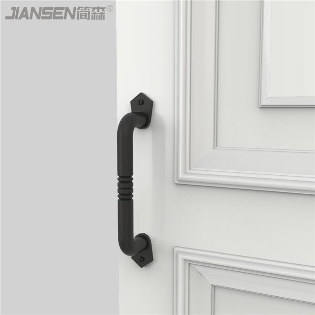
To specify barn door handles for an OEM project, define overall length, bar section, projection, center-to-center hole spacing, mounting arrangement, door thickness, and clearance to the track and lock on one controlled drawing. Do not select or approve a handle from overall length alone. The hole pattern must match the door, projection must leave usable hand clearance without colliding with adjacent hardware, and the fastener stack must match both the handle arrangement and the actual door construction. Because several of these values are not published for the current models, buyers should treat them as approval fields rather than assumptions.
This guide is for technical sourcing teams, product managers, importers, and drawing reviewers. It explains a dimensional system for barn door handles; it does not rank designs or provide an installation procedure. Buyers can first review the barn door handle product category, then use the method below to turn a selected model or custom concept into an auditable OEM specification.
Define the sizing system before choosing a model
A useful handle specification separates dimensions by function. Overall length describes the product envelope, but center-to-center spacing controls the door hole pattern. Projection controls the outward envelope, while grip clearance describes the usable space for the hand. Bar section affects the shape and size of the gripping member. These fields are related, but none is a substitute for another.
Use one datum and one unit system
Nominate a stable door face, door edge, or handle centerline as the drawing datum. State millimeters as the controlling unit if that is the project convention, and label any inch values as reference-only unless both systems have separately controlled tolerances. This prevents rounding from silently changing a hole pattern. The drawing should also state whether dimensions refer to the handle, the door, or the complete assembled stack.
ISO 129-1:2018 provides general principles for presenting dimensions and associated tolerances on technical drawings. It does not set the correct dimensions for a barn door pull. Its value here is the discipline of expressing each requirement clearly and consistently.
Separate every required handle dimension
The buyer’s data sheet should use fixed field names. If a supplier drawing uses different terms, the parties should map those terms before approval. A slash-separated size triplet on a web page cannot safely answer every OEM question, especially when the page does not label hole spacing, projection, or grip width as independent controlled characteristics.
| Specification field | What it describes | Why the buyer needs it | Approval evidence |
|---|---|---|---|
| Overall length | Maximum end-to-end handle envelope | Confirms visual scale and available door area | Dimensioned drawing plus sample measurement |
| Bar or tube section | Width, diameter, or profile of the gripping member | Defines the grasped geometry and mating details | Section view with labeled dimensions |
| Projection | Maximum distance from door face to outermost handle surface | Controls collision risk and the assembled envelope | Side view measured from a named datum |
| Grip clearance | Usable distance between the door face and the inside of the grip | Supports hand access review | Section view at the tightest location |
| Center-to-center hole spacing | Distance between mounting-hole centerlines | Controls drilling and interchangeability | Hole-pattern drawing and verified template |
| Hole diameter and tolerance | Finished door-hole size and permissible variation | Must suit the approved fastener and stack | Door drawing linked to fastener specification |
| Door thickness range | Minimum and maximum approved assembled door thickness | Controls fastener engagement and paired-handle fit | Assembly section for each thickness endpoint |
| Track and lock clearance | Minimum static gaps to nearby operating hardware | Prevents interference throughout door travel | System-level overlay or mock-up |
Treat overall length as a reference, not a hole pattern
Published overall lengths are useful for shortlisting, but they do not disclose the mounting centers. The current category contains 12 products. Among the non-conflicting public examples, stated overall lengths include 201.9 mm for HMBS602, 228 mm for HMBS601, 228.3 mm for HMBS607, 229 mm for HMBS605, 282.7 mm for HMBS612, and 306.5 mm for HMBS606. HMBS681 is described only as 12 inch. HMBS682 and HMBS684 do not publish a size.
| Model example | Published overall length | Published thickness | Center-to-center spacing | Projection / grip width |
|---|---|---|---|---|
| HMBS602 | 201.9 mm | 2.4 mm | Not published | Not published |
| HMBS601 | 228 mm | 4 mm | Not published | Not published |
| HMBS607 | 228.3 mm | 6 mm | Not published | Not published |
| HMBS605 | 229 mm | 2.5 mm | Not published | Not published |
| HMBS612 | 282.7 mm | 4.2 mm | Not published | Not published |
| HMBS606 | 306.5 mm | 2.7 mm | Not published | Not published |
| HMBS681 | 12 inch | Not published | Not published | Not published |
| HMBS682 | Not published | Not published | Not published | Not published |
| HMBS684 | Not published | Not published | Not published | Not published |
The published metal thickness values represented in these examples span 2.4–6 mm. That range describes listed product fields, not a universal engineering recommendation. It also must not be confused with door thickness, bar width, grip clearance, or structural capacity.
Make center-to-center hole spacing a controlled characteristic
Center-to-center spacing, often abbreviated C-C, is the linear distance from the centerline of one mounting hole to the centerline of the other. It should be shown independently from overall length and from the distance to either end of the handle. For a two-hole pattern, a complete definition includes the C-C dimension, both hole diameters, position relative to the door datum, and the applicable tolerance.
No center-to-center spacing is published for any of the inventoried models. No published model page supplies a drilling template, screw size, product weight, projection, grip width, or track/lock clearance. Therefore, a buyer should request these fields on the controlled drawing for the exact revision being sourced. A proportional estimate from a photograph or an overall dimension is not acceptable evidence.
Control orientation as well as distance
A single spacing value does not fully locate a pattern. The drawing must define whether the centerline is vertical, horizontal, or angled; its offset from the door edge; and which face is viewed. For a flush pull paired with an outer pull, the inner and outer geometry should be overlaid in the same coordinate system. Revision, scale, and any “do not scale drawing” instruction should be visible.
Build a drilling template from the approved drawing
A drilling template is a production aid derived from the approved hole-pattern definition; it is not the source of the specification. The controlled drawing remains authoritative. The template should carry the model or project identifier, drawing revision, units, datum edge, orientation, hole centers, hole diameters, and a dimensional verification mark that exposes print scaling errors.
Use a template release checklist
- Match the template identifier and revision to the approved handle and door drawings.
- Show the door face, top direction, closing edge, and reference datum unambiguously.
- Label every center point and distinguish drilling holes from printed reference marks.
- Include a known check dimension so the receiving team can verify 1:1 output.
- State the intended substrate or door construction without inventing a universal hole size.
- Record who approved the template and the date of approval.
- Archive the released file with the corresponding golden sample record.
The HMBS607 and HMBS682 pages state that their arrangements require two drilled holes, but neither page publishes the spacing. That confirms the need for model-specific drawing control rather than filling the gap with a generic template.
Specify single-sided and double-sided assemblies separately
A single-sided pull uses a handle on one face and a fastening arrangement that terminates at, within, or through the door according to the approved design. A double-sided assembly coordinates components on both faces and may use through-fasteners or another defined connection. The bill of materials, sectional view, and door preparation must identify which arrangement applies.
HMBS681, HMBS682, and HMBS684 are described as double-sided variants. Published package contents vary by model: examples list two, four, or six screws, and HMBS682 lists six screws plus one pad. Those counts should not be generalized into a standard mounting pack. Screw diameter, length, thread, head form, and material are not published and require approval for the selected assembly.
Require an assembly section
The section should identify the outside pull, inside component, door faces, any pad or spacer, every fastener, and the engagement condition. It should also expose whether fastener heads, nuts, posts, or recessed parts occupy clearance needed by a lock. If different door constructions share one handle, issue a controlled section for each approved stack rather than relying on a broad “fits most doors” statement.
Match the fastener stack to actual door thickness
Door thickness is a system input. Measure the finished assembly at the mounting zone, including skins, applied panels, trim, plates, or compressible layers that affect the clamped stack. Define both the nominal value and the approved minimum-to-maximum range. Then match the fastener specification and engagement requirement to those endpoints.
Among the cited products, only HMBS682 publishes a numeric door-thickness statement: custom doors up to 45 mm thick. That value belongs to that model’s page and must not be extended to other barn door handles. If a project is considering HMBS682, the buyer still needs the approved screw specification and assembly drawing because those details are not published.
Verify track, lock, edge, and hand clearances
A handle can satisfy its own dimensions and still conflict with the complete sliding-door system. Review the door in closed, opening, and fully open positions. Check the moving handle envelope against track components, hangers, stops, wall trim, adjacent panels, pockets, and the user’s approach path. Review the inner component separately because it may pass close to a wall or overlap another door.
Use a system clearance checklist
- Track and hanger: show the closest distance throughout the full travel range.
- Door stop and anti-jump parts: confirm the projected handle envelope does not overlap their operating space.
- Lock body and keeper: overlay the handle holes, fasteners, backplate, lock, and strike zones.
- Door edge: define enough edge distance for the approved door construction; do not assume one universal value.
- Wall and trim: check the inside component, fastener heads, and fingers at the tightest position.
- Paired panels: evaluate crossing handles and their swept envelopes.
- Grip space: dimension the minimum usable clearance rather than reporting maximum projection alone.
The current pages do not publish numeric track or lock clearances. Buyers should coordinate the handle layout with the chosen barn door lock range and the actual track drawing. The result belongs in the project assembly, not in a generic product assumption.
Check accessibility requirements at project level
Accessibility is determined by the complete opening and the rules applicable to the project. The U.S. Access Board guide for entrances, doors, and gates notes that pulls should provide sufficient knuckle clearance and explains an operable-parts height range of 34 to 48 inches for covered doors and gates. A project team may use this source as a review reference where relevant.
This citation does not prove that any Jiansen product, drawing, opening, or project complies with accessibility requirements. The responsible designer should evaluate mounting height, operating space, maneuvering clearance, force, door movement, and local requirements for the complete assembly.
Release a complete OEM drawing checklist
A controlled drawing package turns a product selection into a reproducible requirement. For related sourcing context, see the barn door hardware OEM/ODM buyer’s guide. For the handle itself, release the following fields before sample authorization:
- Project name, handle model, part number, drawing number, and revision.
- Controlling units, scale status, general tolerances, and named datums.
- Overall length and all envelope dimensions.
- Bar, tube, or grip section dimensions with section-view location.
- Maximum projection and minimum usable grip clearance.
- Center-to-center spacing, hole diameters, positional definition, and tolerances.
- Single-sided or double-sided arrangement and a complete assembly section.
- Finished door-thickness range and door construction at the mounting zone.
- Fastener diameter, length, thread, head, quantity, and engagement requirement.
- Pad, spacer, flush pull, backplate, or other mating-component details.
- Track, wall, door-edge, paired-panel, and lock clearance requirements.
- Inspection method, measuring equipment, sampling reference, and acceptance record.
- Linked drilling-template identifier and golden-sample identifier.
- Approval names, dates, revision history, and change-control method.
Approve a physical sample against the released data
Sample approval should close the gap between a two-dimensional drawing and the real assembly. First confirm document identity: model, revision, template, and bill of materials must agree. Then record actual values for overall length, bar section, projection, grip clearance, hole spacing, hole diameter, and relevant interface dimensions. Compare results only with agreed tolerances; do not create tolerances after seeing the sample.
Evaluate the sample in the representative door stack
Use a representative finished door section at both approved thickness endpoints, plus the intended inner and outer components. The review should confirm alignment, fastener engagement, stable seating, and the absence of interference with the project track and lock geometry. Keep photographs and signed measurements with the retained sample. If any dimension changes, update the drawing and template together, then repeat the affected approval checks.
Jiansen’s public model data can support the initial shortlist, but the signed drawing and approved sample should govern fields that the web pages do not publish. To request model-specific dimensional documents, use the contact page and identify the target model, door stack, and required drawing fields.
Plan incoming inspection around critical dimensions
Incoming inspection should begin with identity and revision control. Inspectors need the approved drawing, current template reference, golden-sample record, purchase specification, and measurement method. Separate critical interface characteristics—especially hole spacing, hole size, projection, and fastener compatibility—from informational dimensions. Record equipment identity and measurement results in the same units as the controlled drawing.
ISO 2859-1:2026 provides a framework for acceptance sampling by attributes for lots. It does not prescribe a project’s acceptance quality limit, inspection level, or critical-defect policy. The buyer and supplier must define the applicable plan and switching rules in their agreement rather than inventing an AQL after goods arrive.
Use an incoming inspection record
- Confirm carton, model, assembly type, lot identity, and drawing revision.
- Verify included component identity and count against the approved bill of materials.
- Measure controlled dimensions using the agreed method and calibrated equipment.
- Check the hole pattern with an approved gauge or verified template.
- Compare the assembled interface with the retained sample where the plan requires it.
- Record nonconformities by characteristic and disposition; do not average away an interface failure.
- Preserve traceability from results to lot, sample units, inspector, and decision.
Frequently asked questions
What dimensions should an OEM barn door handle drawing include?
It should include overall length, bar or tube section, maximum projection, minimum grip clearance, center-to-center hole spacing, hole diameters and tolerances, door-thickness range, fastener details, mounting arrangement, and track and lock clearances.
Is overall handle length the same as center-to-center hole spacing?
No. Overall length is the end-to-end envelope, while center-to-center spacing is the distance between mounting-hole centerlines. A buyer needs both values because one cannot be calculated reliably from the other.
Are hole-spacing values published for the listed barn door handles?
No. The inventoried product pages do not publish center-to-center hole spacing, so the value must be confirmed on the controlled drawing for the selected model and revision.
What door thickness do these barn door handles fit?
Only HMBS682 publishes a numeric limit, stating custom doors up to 45 mm thick. Other models need a model-specific assembly drawing and fastener review; the HMBS682 limit should not be applied to them.
What is different about sizing a double-sided handle?
A double-sided assembly must coordinate components on both door faces, the complete fastener stack, door thickness, hole pattern, inner clearance, and any flush pull or pad. The assembly section and bill of materials should identify every mating part.
How should buyers approve a drilling template?
Approve it against the released hole-pattern drawing, checking model, revision, units, datum, orientation, center locations, hole diameters, and a known scale-check dimension. Archive the approved template with the corresponding sample record.
